Стремитесь к лидерам отрасли по производству конденсаторов с передовыми технологиями и ценами.


Как быстро определить одинаковые и противоположные клеммы трансформатора с помощью осциллографа
Some transformers do not have their phasing dots marked, so we need to identify them ourselves. There are many methods to determine the identical terminals, such as using a multimeter, an LCR meter, or a battery with an LED. This article introduces a method using an oscilloscope to find the identical terminals.
Measurement Principle
A signal generator is used to input a signal into one winding of the transformer. Then, an oscilloscope with two channels is used to measure the signals from the two windings. If the signals are in phase, it indicates that the positive terminals of the oscilloscope probes are connected to the identical terminals of the windings. If the signals are out of phase, then the positive terminals of the probes are connected to opposite terminals.
Measurement Tip: If measuring a high-frequency transformer, it is recommended to use a high-frequency signal, such as 10kHz. If measuring a regular transformer, a 50Hz frequency signal is suggested. The amplitude should be set to the maximum output of the signal generator.

Measurement Process
The transformer measured in this article is a high-frequency transformer from a 5V mobile phone charger, as shown in the figure below.

The signal used has a frequency of 10kHz and an amplitude of 20V sine wave, as illustrated below.

The signal is connected to one side of the winding according to the measurement principle diagram. Then, the oscilloscope probes measure the signals on both windings, as shown in the following figure.

In the figure above, the left side shows the input signal, and the right side shows the induced signal from the winding.
The oscilloscope waveform is shown below:

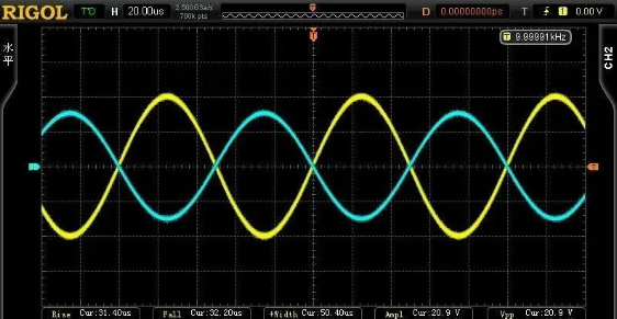
In the above figure, the yellow CH1 represents the input signal, and CH2 represents the output signal. This indicates that the positive terminals of both oscilloscope probes are connected to the identical terminals. Additionally, from the waveform amplitude, it can be observed that the turns ratio of the two windings is approximately 10:1, as the amplitude has attenuated by about 10:1.
If the CH2 probe’s positive terminal and ground clip are swapped, the waveform appears as shown in the figure below:
It can be seen that the waveform is inverted because the positive terminals of the two oscilloscope probes are now connected to opposite terminals.
Здание 8&9&12, Фабрика стандартизации электронной информации, зона экономического развития Сусон, провинция Аньхой, П. Р .Китай.
R&Д-центр: Штаб-квартира Дунгуань
Производственный центр: Сусонг, Аньцин, Аньхой